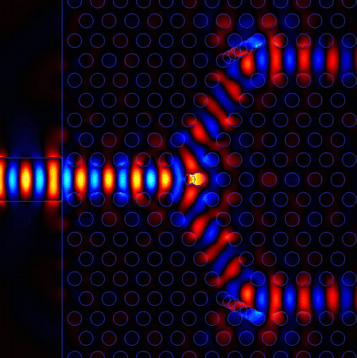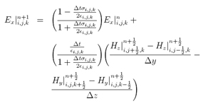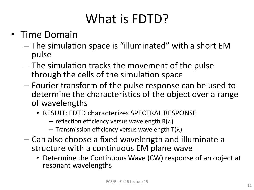
Conductors such as copper can be simulated in FDTD, but since the equations for computing the fields in copper material are more complicated than those for a perfect conductor, the calculation will take longer. Because of the simplicity of the calculation for these materials, it is better to use a perfect conductor rather than a real conductor whenever feasible. Perfectly conducting electric and magnetic materials are simulated by setting the electric or magnetic field to zero for any cell edges located within these materials.
#Fdtd free
All FDTD cells are initialized as free space and the fields at all cell edges are updated using the free space equations unless another material is added to replace the free space. The most basic material of course is free space.

#Fdtd software
Figure 5 shows a larger view of the surfaces of the conformal mesh.įDTD simulation software is capable of simulating a wide variety of electric and magnetic materials. In Figure 4b the same part of the phone mesh is shown, this time using a type of conformal treatment for cells which contain portions of the surface of an object. A small portion of the FDTD mesh of the phone is shown in Figure 4a using simple rectangular cells. For clarity, the visibility of many of the parts, including the outer case, has been turned off to show the region near the antenna. These “conformal” cells can be further refined to account for curvature of the object surface within the volume of the cell.įigure 3 shows the geometry of a portion of a mobile phone. Another refinement can allow for objects whose surface intersects the cell at arbitrary angles with respect to the principle axes.
#Fdtd update
Within a cell, the standard update equations of FDTD may be refined in many ways, for example to allow for wires that are thinner than a cell size. This allows more cell edges to be placed in regions of strong fields, such as around small features of highly conductive material. The spacings between cells in the x, y, and z-directions can vary throughout the problem space. The square Yee cell of Figure 1 can in general be rectangular. This typically means that all field values have decayed to essentially zero (at least 60dB down from the peak) or a steady-state condition has been reached. A calculation must continue until a state of convergence has been reached.

The surrounding fields will propagate the introduced waveform throughout the FDTD grid appropriately, depending on the characteristics of each cell. At each step in time, the value of the waveform over that time period is added into the field value. One method emulates exciting a geometry at discrete locations by applying a sampled waveform to the field update equation at one or more locations. In practice the cell size will often be smaller than this in order to resolve dimensions and features of the structure to be simulated such as the thickness of a substrate or the length of a wire.Īn excitation may be applied to an FDTD simulation in many different ways. A general rule of thumb sets the minimum resolution, and thus the upper frequency limit, at ten cells per wavelength. The cell size, the dimensions of the small box, is the most important constraint in any FDTD simulation since it determines not only the step size in time, but also the upper frequency limit for the calculation. Each small box shown in the figure represents one FDTD cell.

By associating many cell edges with materials, a geometrical structure can be formed within the FDTD grid such as the dielectric sphere shown in Figure 2.

Introducing other materials or other configurations is handled in a similar manner and each may be applied to either the electric or magnetic fields depending on the characteristics of the material. By joining numerous end-to-end cell edges defined as perfectly conducting material, a wire can be formed. For example, to add a perfectly conducting wire segment to a cell edge, the equation for computing the electric field can be replaced by simply setting the field to zero since the electric field in a perfect conductor is identically zero. Within the mesh, materials such as conductors or dielectrics can be added by changing the equations for computing the fields at given locations. Each cell will also have three magnetic fields originating on the faces of the cell adjacent to the common node of the electric fields as shown in Figure 1. The electric fields at the other nine edges of the FDTD cell will belong to other, adjacent cells. Each FDTD cell will overlap edges and faces with its neighbors, so by convention each cell will have three electric fields that begin at a common node associated with it. When many FDTD cells are combined together to form a three-dimensional volume, the result is an FDTD grid or mesh.


 0 kommentar(er)
